Hi-End Transformer-Coupled Tube Headphone Amplifier
With Digital Input
Andrea Ciuffoli project
Non è un kit
le uniche informazioni disponibili sono illustrate in questa pagina i componenti sono a scelta dal ns sito.
is Not a Kit
all informations available are showed in this Page, components are to choose from our web site
About one year ago I designed the
Top-Level OTL Tube Headphone Amplifier and more recently, I designed the
No-Compromise Tube Headphone Amplifier, where each channel uses an E182CC tube
(both sections) to match the low impedance of headphones. The results of these
OTLs are very good and the sound is better than any other OTL headphone
amplifier using regulator tubes such as 6080 or 6AS7.

But, in my continuing search for the best sound, I have created these projects. Looking into the online datasheets of the Lundahl web site, I discovered the LL1630 transformer. The LL1630 has a wide frequency response from 10Hz to 40kHz (+/-0.5dB) and a good inductance value to build a perfect headphone amplifier to drive headphones with impedances from 150 to 600 ohms.
There are 2 ways to better the
performance of the OTL amplifers: use octal tubes (more linear than noval), or
use a single stage instead two. After many listening tests and simulations on
Spice3f4 to obtain improved sound and the same or better electric performance of
the OTL solutions, I have designed an amplifier based on the LL1630. Later, I
will show a DAC input stage using the Lundahl LL1566 and LL1527XL transformers.
The Amplifier
Designs
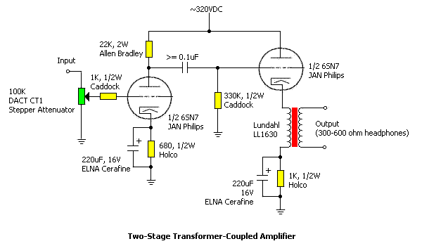
The design is a two-stage, but
with an octal tube - the more linear indirect-heating 6SN7. These tubes and the
cathode follower configuration of second stage give very low distortion, low
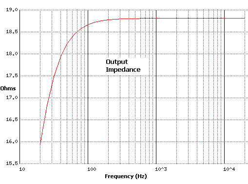
output impedance and an incredible low frequency response.
-
Ftl = less than 10Hz
Rout = less than 19 ohms
THD = always less than 1%
To get more gain, a 6SL7 tube could be used in input stage, but a higher power supply voltage, about 450V, is suggested. Both the 6SN7 and 6SL7 can work at 450V, requiring only changes to the bias resistors on cathode. With the 6SL7, the anodic resistance must be about 100K 1W instead 22K 2W.
About passive components types, I don't leave many choices: Allen Bradley resistors on anode, Holco or Caddock resistances on cathode, ELNA Cerafine capacitors on cathode and power supply, and the DACT stepper attenuator. For all my new projects, I am using the very good ELNA Cerafine capacitors that I love and which The ELNA Cerafine capacitors contain super fine ceramic particles which, through chemical reaction, improve the discharging speed between the anode and electrolyte with very low distortion. Any other electrolytic or polypropylene capacitor is trash. Only the Blackgate WKZ could give better sound, but I have not tested it.
For interstage capacitors, the best choice would be copper film-paper in oil, but now I am using the ERO KP1832 and the sound quality is very high.
I am using a DACT stepper
attenuator instead of the normal ALPS or NOBLE solution, because the the sound
is clearer. At this time I am using this amplifier with the Sennheiser HD580
(300 ohms).
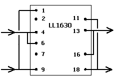
The LL1630 transformer here is
used with parallel connection of the primaries. It must be gapped for a 5mA DC
current, so that in parallel connection, it will run fine with the 9.5-10mA bias
current of the output tube. When ordering this component from Lundahl, ask for
LL1630/5mA. The maximum current output is 10ma (bias current of output stage) x
7.2 (transformer ratio) = 72mA.
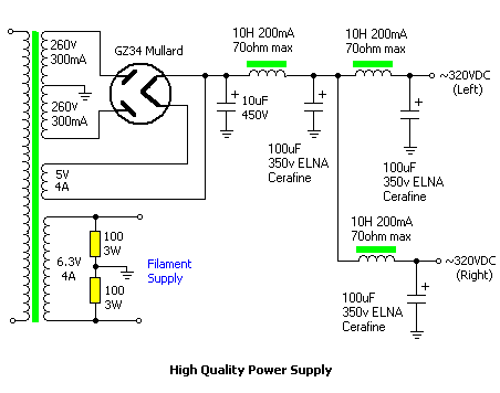
About the power supply, I suggest
this above design that gives the best result, but is not very cheap to
implement. The GZ34 Mullard could be replaced with 5R4 RCA or mercury type tube
diodes.
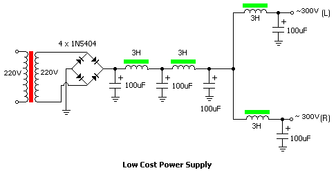
To reduce the cost or to make a first test of this amplifier, you can build the following simple but good power supply using an isolation transformer (220V:220V or 110V:220V) The capacitors could be motor-start MKP types. The inductors could be neon-type inductors for 65 Watts, but, of course, the neon inductors have no gap, so some distortion is generated by the DC current flow.
Here are some test results for this project:
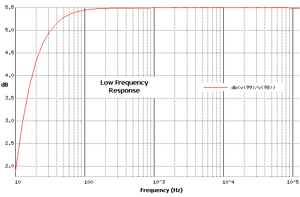
low
frequency cut-off is about 13Hz, but here I am using the LL1630/10mA instead
LL1630/5mA.
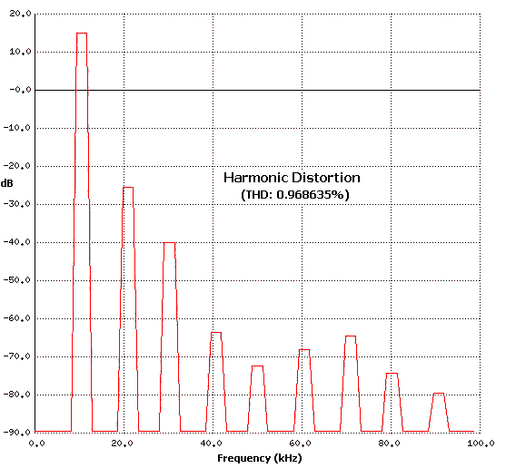
Only second and third harmonics
are present up -60dB. The decay is linear, so is very natural like the other
single-ended designs. In any case, what is very important is that the sound is
more natural than the OTL versions!
The Digital Input Stage
About the DAC input stage, I have many solutions:
-
1) The Extreme DAC board by DiyZone
(output stage wth op-amp is not used).
2) The Stefano Perugini board, available for $30, including a very good power supply using a tube diode rectifier for the analog supply of the DAC.
3) the Evaluation Board CDB4390 from Crystal Semiconductor (output stage wth op-amp. is not used).
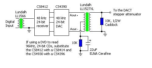
All these DACs use the same chip
set: CS8412 and CS4390. The above schematic shows the basic modifications. I
suggest putting the LL1566 Pulse transformer at the input in any DAC solution
when not using an optical cable. The best design would use 2 LL1566
transformers, as specified in the application guide on the LL1566 datasheet. The
LL1566 serves to separate the transport from the DAC.
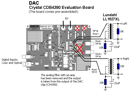
I am using now the Crystal CDB4390 evaluation board, because it comes pre-assembled. To get the Crystal CDB4390
I will start soon to test the new Crystal CDB4397, which uses the new Crystal DAC chip CS4397, the first audio DAC that offers both 120 dB dynamic range performance -- the highest in the industry -- and compatibility with the next generation audio formats: DVD-Audio (24-bit, 192 kHz sampling rate), SACD (Direct Stream Digital Technology).
The above diagram shows how to connect the LL1527XL to the Crystal DAC. The output stage active filter is replaced by a Lundahl LL1527XL transformer, which is configured as a bandpass filter. The RC network at the input of the LL1527XL is a high pass filter. It has a threshold frequency ft = 1/ (R * 2 * pi * C). With values of 10K and 22uF, the network has a threshold frequency of about 0.72Hz (-3db).
The high frequency cutoff is the high frequency limit of the LL1527XL (about 150kHz - see the LL1527XL datasheet). The DAC output noise is very low until 128xFs, where we can get the clock. The LL1527XL output stage does not have the same high frequency cutoff as the opamp filter (about 50kHz @ 12dB/octave), but a wider high frequency range. The 2-pole active filter used by Crystal (and also by Burr-Brown) gets the lower distortion value to show on the datasheet, but I don't search the lowest distortion, but the best sound. The high frequency rolloff is only 6dB per octave; I cannot detect any digital noise at the output of the LL1527XL, so this is enough to use it.
This modification will only work with DACs that have push-pull outputs. With single-ended DACs, such as the Burr-Brown DAC, a capacitor should be added before the transformer to reduce the high frequency noise of the DAC. This circuit should be tested to prevent problems.
The DAC sounds better (very
natural) without the active filter, because with the LL1527XL, these is no
feedback on all the system, and so no compression of the sound. The difference
in sound with the active filter is terrible (another world) !!!! Then you need
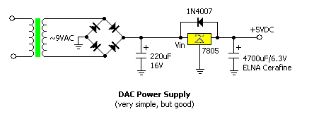
only to assemble a simple power supply such as the following:
Addendum
1/4/2000: updated DAC section.
Torna all'indice Back to index
Prezzi e prodotti aggiornati sul nuovo sito Audiokit e-Shop cliccando qui !
Update prices & products on new e-Shop Audiokit website click Here
mercoledì 02 luglio 2014