NewClassD
Siamo distributori per l' Italia e possiamo fornire tutti i prodotti presenti sul sito del costruttore

D-Clock Audio Reference Clock Generator
Announcing the new product line
of High End Audio Reference Clocks for upgrading of CD
players, DVD players, SACD players, Computer Soundcards,
etc.
Several new - never seen before - features will be
introduced to the market for the very first time in these new
Super Clocks. And the performance level is second to
none.
Ci stiamo Riorganizzando per eseguire di nuovo gli UP-Grade dei lettori CD presso i nostri laboratori !
al più presto altri circuiti di UP-Grade tenete d'occhio le pagine !
|
Su Ordinazione ! on reservation ! Tempi di consegna approssimativi presso il ns punto vendita 7- 20 giorni On reservation, approximate delivery Time at our shop 7 - 20 days |
|
Description |
Euro / unit Tax included Italia & CE |
Euro / unit Without Tax Extra CE |
| D-Clock 8.467200 MHz - included cables (without power supply) | ||
| D-Clock 11,289600 MHz - included cables (without power supply) | ||
| D-Clock 12,288000 MHz - included cables (without power supply) | ||
| D-Clock 16,934400 MHz - included cables (without power supply) | ||
| D-Clock 24,576000 MHz - included cables (without power supply) | ||
| D-Clock 27,000000 MHz - included cables (without power supply) | ||
| D-Clock 33,868800 MHz - included cables (without power supply) | ||
| D-Clock 45,158400 MHz - included cables (without power supply) |
IL PREZZO - NON - INCLUDE L'INSTALLAZIONE !!!
Accuracy: +/- 1ppm
Jitter: 1.5pS
Df (9-24V): Max 1Hz
Control Functions: Host Vcc
Power Supply Requirements: 9.00 - 24.00 Volts DC 20
Importante !
leggere le seguenti istruzioni...si, sono in Inglese ma sono tecnicamente abbastanza comprensibili, cercheremo comunque di tradurle al più presto, eventualemente potete documentarvi genericamente ai nostri vecchi link Old CD Up-Grade o direttamente in rete dove normalmente trovate di tutto !
Vi preghiamo quindi di NON interpellarci in merito a suggerimenti di installazione sulle varie macchine, in special modo quelle di nuova generazione, al momento NON siamo in grado di fornirle, per cui se ritenete di essere in grado di installare il Clock da soli o per mezzo dell'aiuto di un Vs tecnico OK ! altrimenti non Vi possiamo fornire altro aiuto in merito.
|
Noise and Jitter Free Clock
Signal. Due to the special output configuration, the clock signal is absolutely noise and jitter free, and that is the most important feature of a reference clock. [Here seen in the 3V mode]. In terms of sound quality you get a rock solid sound stage, with a wide, deep and natural placement of the performers. That is nothing new, when using an audio clock. But how many times have you heard about people spending vast amouts of money optimizing the power supply of their clocks? Well with the D-Clock it's no longer necessary. The reason for using an external power supply is not a matter of getting more power, or even noise free power. Every audio clock has it's own low noise power regulator to eliminate voltage drop and high frequency noise. And when you add a new mains transformer to your supply, you actually get a lot of new capacitively coupled noise into your audio clock power supply. Still the addition of a high quality power supply is a significant improvement. That is because the external power supply is the only way you can eliminate ground loops from the CD player's power supply to the sensitive digital/analog converters. Or was! |
|
|
Isolated Clock Injection
Point. As a unique feature, the clock signal is isolated from the power supply GND, so you get no GND loop, and also you get no Mains Noise injection. This is achieved with a 100 MHz micro pulse transformer, with an isolation capability of 1500V. The Power GND and the sensitive Digital GND can no longer see each other, and so you get a cleaner clock signal. Not only does the isolator remove any power supply noise, and GND loop, it also makes the connection to the CD / DVD player much simpler. Remove the Crystal, and two capacitors, form the CD player, and connect the cable. The capacitor in series with the clock signal is a special PET type with good sound qualities. Please Note, the blue LED is used for indication only. |
|
|
When we say 'Micro' ..... . The clock isolation transformer consists of two microscopic toroid transformers, (around 3 mm diameter). One is used for the isolation function, the other is a common mode choke, that prevents noise spikes from the outside, entering the reference clock backwards. This particular isolator transformer is designed for high speed pulse communication, such as found in local area networks. (Up to 100 MHz). The whole package shown here is just 12.7 mm (0.5') wide. |
|
|
Ultra Low Noise Power
Regulation. The Power Supply Regulation for any reference clock is critical. We use a double pre regulated version with a central reference type LM329DZ. This reference has the lowest inherent noise, and thus needs less post filtering than most other regulators. The internal clock circuit core runs on it's own separate supply, and output stage can be run on either 3 or 5 V to connect to various players. DVD players usually take 3V mode, while CD players usually uses 5V. You can experiment for the best result. Power Connection to the outside world is achieved with a 'Micromatch' connector, with cable 30 cm included. Directly after that a set of GND and Power filtering chokes with special Q dampers. These remove noise above 2 MHz, also from the GND of the power supply. This is only possible because of the special output isolation, and makes the D-Clock simulate battery operation. A pair of power holding capacitor with totally 1100uF is used to stabilize the power supply for the D-Clock. This is smaller than found on some other clocks. The D-Clock however has around 4 times lower power consumption and so a large capacitor is not needed to hold the supply up the same amount of time. And more importantly a smaller Low-Z capacitor has much better high frequency filtering capability than a large can. |
|
|
Protective Ground Plane. The inside of a CD or DVD player is a very noisy environment, as thousands of small digital circuits inside the LSI chips generate electromagnetic noise. That is why you should use a solid ground plane to act as a shield against these noises, and prevent them from degrading the performance of your reference clock. Normally this is solved in high-end clocks by using 4 layer PCB with internal GND plane. However we have found that the minute capacitances from the pads to the GND plane, with only a very thin layer of epoxy resin as a isolator, is enough to affect the performance and temperature stability of the clock. The epoxy resin is not a very temperature stable dielectric material. One solution is to use Teflon based PCB, but that is both very expensive and also tends to give the sound a bit of excessive dryness. Our solution is to reduce to 2 copper layers, but use the whole 'bottom layer' as a GND plane. This takes a lot of maticulous planning on the layout part, you have to keep all the signal tracks on the top layer, but pays itself in 4 times lower stray capacitance. As you can see the GND plane near the output plug belongs to the CD player's sensitive digital GND, and is isolated from the rest of the D-Clock GND plane. |
|
| You can disable the clock output with a
voltage signal. This is useful if you have a constant
power source for your clock (like an external PSU or in
a DVD where the power is controlled by a microprocessor,
so your Clock power is on, while other circuits are
turned off). If you use a simpler clock in this case,
your CD or DVD player can be damaged. In the D-Clock we have provided an effective solution. The VCC of the host player can be connected to the 'Host VCC' pad, and the Host VCC detector activated. When the D-Clock detects voltage 3.3 or 5V on this pad, the clock signal is admitted. When power is off, the clock signal is stopped to prevent latch-up of the input circuit of the player. In most normal cases however, the clock power is turned on and off with the host player, so you can 'Ignore' (Default) the host VCC. This is done by leaving the 'Ignore' pad shorted with solder. In other words you don't have to do anything. If you want to use the Host VCC detector, you must remove the solder from the 'Ignore' pad. |
|
| Power Supply for the D-Clock can be derived from the
CD or DVD player very easily. Use a Voltmeter to
establish the voltage across the power supply capacitors
(start with the biggest cans in the player). Since the
output is isolated, you don't have to worry about
whether the particular part of the PSU is connected to
the digital processors or not. This makes successful
installation of D-Clock much simpler than most
clocks. If the voltage is steady when the player is on, and in the range of 9 - 25 V DC, then you can use this power source. The red or blue wire of the power cord is GND, while the grey one in the other side of the ribbon cabe is +. The two first, and two last wires are connected with each other in the connector. |
|
| Some CD or DVD players run with 5V supply, others
with 3.3V. Most low cost clocks only give you one
option, and that is 5V. If you connect a 5V clock to a
3.3V CD or DVD player, you may very well damage the
sensitive circuits. That is why we provide you with a
voltage setting on D-Clock. This allows you to adapt the
output closk signal to fit your player perfectly. Use a
simple Voltmeter to determine whether your player uses
3.3V or 5V power supply. You can find the voltage on the
small brown components sorrounding the chip, where the
original crystal of your player is connected. By default
the D-Clock is set to 3.3V (3.3Vpp clock signal). If you
want to set it to 5V, simply add solder to the '5V'
bubble. (5Vpp clock signal). Power Supply Cable and Clock Signal Injection Cable are included with every D-Clock. |
|


Interface to a DIP 8 oscillator footprint.
Many CD players are equipped with a DIP8 crystal oscillator like this one:
Click to Enlarge
Remove the crystal oscillator from the main board, and connect the D-Clock cable as seen here:

Click to Enlarge
Visto dal lato componenti !
Prezzi e prodotti aggiornati sul nuovo sito Audiokit e-Shop cliccando qui !
Update prices & products on new e-Shop Audiokit website click Here

D-Clock Neutron Star Clock Generator
A list of new - never seen before - functions is introduced with this high end reference clock, but not least new mindblowing performance will set new standards in the world of high end audio clocks.
|
Su Ordinazione ! on reservation ! Tempi di consegna approssimativi presso il ns punto vendita 7- 20 giorni On reservation, approximate delivery Time at our shop 7 - 20 days |
|
Description |
Euro / unit Tax included Italia & CE |
Euro / unit Without Tax Extra CE |
| D-Clock Neutron Star 8.467200 MHz - included cables (without power supply) | ||
| D-Clock Neutron Star 11,289600 MHz - included cables (without power supply) | ||
| D-Clock Neutron Star 12,288000 MHz - included cables (without power supply) | ||
| D-Clock Neutron Star 16,934400 MHz - included cables (without power supply) | ||
| D-Clock Neutron Star 24,576000 MHz - included cables (without power supply) | ||
| D-Clock Neutron Star 27,000000 MHz - included cables (without power supply) | ||
| D-Clock Neutron Star 33,868800 MHz - included cables (without power supply) | ||
| D-Clock Neutron Star 45,158400 MHz - included cables (without power supply) |
IL PREZZO NON INCLUDE L'INSTALLAZIONE !!!
| New low distortion 3 transistor hybrid oscillator. |
| Precision better than +/- 0.2 ppm. |
| Precise temperature stabilization at 37 degress C. |
| Double insulated voltage regulators. |
| Power Supply Noise detector. |
| Insulated Signal Injection Point. (Voids Ground Loops). |
| Ultrastable PTFE ( Teflon ) RF Trimmer. |
| Mechanical size : 107 x 44 x 12 mm (p 25 mm). |
 |
Rather than the usual RF shielding metal box, which doesn't exactly spell resonance free (try and tap on it), we used a special RF absorbing foam, as used in RF measurement laboratories. This cell foam also has a dampening effect on any mecanical vibration, that might reach the PCB itself. |

The Neutron Star has a few special features. A circuit
constantly monitors the noise on the power supply rails, if
the noise is unacceptably high, a RED LED will light up to
tell you, that you can benefit from using a cleaner power
supply.
The crystal and oscillator is placed on an
isolated pad of the PCB, where power resistors and a
thermostat keeps every temperature sensitive component at a
constant 37 degrees centigrade. This allows for ultra high
frequency stability. A green LED on the PCB will light up,
when the correct temperature is stabilized. If it gets too hot
or too cold, the green LED will turn off. Usually it takes a
few minutes for the thermostat to reach the correct
temperature, this is because we want to keep the power supply
current of the Neutron Star absolutely constant. So the
heating elements are kept to the lowest possible power
consumption.
Should you wish even further power supply
current stability, you can add a solder bubble, to select
'balanced operation' of the heating system. This means that
when the temperature is reached, and the heating power drops
off, the exact same amount of power is dissapated in dummy
resistor elements. So the power supply current will become
dead stable as well.
We adapted the successful
potential isolator from the D-Clock, and to satisfy the users
where the Neutron Star replces a metal can oscillator we added
a special RF schottky diode, to move the DC potential up to
the right level.
We aimed at making the Neutron Star
the most advanced and highest performning reference clock on
the market, while still keeping it on an acceptable price
level. And the result should speak for itself...
Voltage Reference Noise.
A particularly important issue when designing an ultra performance clock is voltage reference noise. This is because you can filter the reference noise out with capacitance, but only in the higher frequencies. At lower frequencies, where the noise is most critical, capacitance will not remove the noise effectively. Therefore we had to look for the best available references in the world, for the Neutron Star Clock.We found that some of our competitors are using the AD589, in their reference clocks costing considerably more than D-Clock Neutron Star. So we considered this reference as an option. However it soon turned out that the AD589 is far noisier than the reference we usually favour, for critical applications, including our regular D-Clock. The LM329. Look at these figures, and compare yourself: (Both curves taken off the datasheets of the respective references).

|
 |
| AD589 Noise Figures. | LM329 Noise Figures. |
Just from the raw curves you see that LM329 exhibits 75-112 nV/Hz while the AD589 is far noisier at around 200 nV/Hz. But that's not the whole story. The AD589 is a 1.2V reference, so to run at 3 or 5V you have to amplify the reference voltage by 2.5 or 4.17. When you amplify the Zener voltage, you naturally also amplify the noise. So at 5V the noise of the AD589 is more like 800-900 nV/Hz. The LM329 on the other hand is a 6.9V reference, so you have to divide the voltage by 1.38, also dividing the noise slightly. So the real figures are:
AD589: 800-900 nV/Hz
LM329: 55 nV/Hz.
As you see AD589, generates around 14 times more noise than LM329. Even at 10Hz, where the LM329 is at it's weakest point, the AD589 is still 9 times noisier (at 5V rail voltage). Noise in the Zener reference usually translates directly into phase noise on the clock signal delivered.
The D-Clock Neutron Star went into production on May 29th 2008, more information will be publicised soon. Neutron Star will be an addition to our product programme as a extreme performance / cost no object alternative to D-Clock. D-Clock is very successful, surpassing even 3 times more expensive competitors, and will continue in our programme for the next years.
 |
A Neutron Star is the remains of the collapsed core
after a massive star has exploded in a Supernova. The
Neutron Star is about 10km in diamter, but has the mass
of our sun. This means it is extremely dense, actually a
teaspoon of neutron star material would weigh millions
of tonnes. Because of the small size, and huge mass,
rotating Neutron Stars are impervious to outside
gravitational disturbances and thus have very stable
rotational speeds, over millions of years. [Read More about Neutron Stars] |

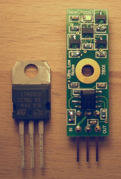
UWB Voltage regulators
The UWB Regulator is a high end replacement for 78XX and 79XX regulators found
in CD / DVD players and other audio equipment. For example 7805, but also other
voltages are produced in UWB. (Even special ones upon request).
Ci stiamo Riorganizzando per eseguire di nuovo gli UP-Grade dei lettori CD presso i nostri laboratori !
al più presto altri circuiti di UP-Grade tenete d'occhio le pagine !
|
Tempi di consegna approssimativi presso il ns punto vendita 7- 20 giorni On reservation, approximate delivery Time at our shop 7 - 20 days |
|
Description |
Euro / unit Tax included Italia & CE |
Euro / unit Without Tax Extra CE |
| DX7803 3,3V UWB regulator | ||
| DX7805 5,0V UWB regulator | ||
| DX7808 8,0V UWB regulator | ||
| DX7809 9,0V UWB regulator | ||
| DX7812 12V UWB regulator | ||
| DX7815 15V UWB regulator | ||
| DX7903 -3,3V Negative UWB regulator | ||
| DX7905 -5,0V Negative UWB regulator | ||
| DX7908 -8,0V Negative UWB regulator | ||
| DX7909 -9,0V Negative UWB regulator | ||
| DX7912 -12V Negative UWB regulator | ||
| DX7915 -15V Negative UWB regulator |
IL PREZZO - NON - INCLUDE L'INSTALLAZIONE !!!
Prezzi e prodotti aggiornati sul nuovo sito Audiokit e-Shop cliccando qui !
Update prices & products on new e-Shop Audiokit website click Here
|


Prezzi e prodotti aggiornati sul nuovo sito Audiokit e-Shop cliccando qui !
Update prices & products on new e-Shop Audiokit website click Here
mercoledì 02 luglio 2014