LClockXO Istruzioni specifiche per il Montaggio
(Q-R)
Attenzione, sono indicazioni indicative ! non possiamo conoscere i dettagli di ogni apparecchio
QUAD 66
|
Frequenza di clock |
11,2896 MHz |
|
Convertitore |
Philips TDA1541A |
Remove the two black screws on the middle of the bottom plate. Remove the screws by both sides under the bottom plate. Lift the top part away. Remove the two screws in each side, holding the back panel. Push the back panel back away from the rest of the player. Remove 4 screws, holding the CD transport, of which two are placed under the CD tray. Look in the hole in each side of the tray, while pushing the tray out. The two screws will appear when the tray is all out. Remove the screws holding the main Circuit Board, also the four holding the mains transformer, and the one in the corner by the Line out plugs. Last remove the clips by the 'Open' button. Unplug the two PCB connectors by the display, now the entire Main Circuit Board, can be easily removed from the assembly. Remove the crystal unit marked '11,2896' it is a shiny metal can part, found some 10 cm. (4 inches) from the line out plugs. Also remove the two surface mounted capacitors connected to the crystal unit on the Solder side. (There are only the two in question). Surface Mounted Devices, and best removed by alternating the Soldering iron, in order to keep both ends melted. Then You can push the component away from the copper pad, and then pick it up with at tweezer. Connect LClock Out (Red twisted wire) to the pcb solder pad of the crystal unit, closest to the CD transport . Connect LClock Gnd (Blue twisted wire) to the wire link at the 'foot end' of SAA7220, closest to the crystal unit. Connect LClock +12V (Red single wire) to the 33 Ohms resistor (orange orange black gold) found very close to the Line Out plugs. Use the terminal closest to the CD transport.
REGA PLANET
|
Frequenza di clock |
16,9344 MHz |
|
Convertitore |
Burr Brown PCM 1710U |
Remove the screws on the bottom of the player, and lift the top part gently away from the bottom. Be careful the tre wires to the lid switch dont come off, they are soldered directly to the PC Board. Shoul it happen, the red wire goes to +5V, the Black to Gnd and the Green wire to SIG. Carefully remove the flex cable to the CD transport from the socket. Remove screws holding the Main Board, remember the one in the corner by the mains transformer. Remove Crystal unit X7, and the two capacitors marked C2 ( ...? ). Connect LClock Out (Red twisted wire) to the pcb solder pad of X7 closest the front of the CD player enclosure. Connect LClock Gnd (Blue twisted wire) to the pcb solder pad of C2 closest to the mains transformer. Connect LClock +12V (Red single wire) to + on LClock XO Power Supply (Required). Remember to also connect LClock ground to the XO power supply. Best taken from the minus of the 10.000 uF Capacitor.
ROTEL RCD-945AX
|
Frequenza di clock |
16,9344 MHz |
|
Convertitore |
Philips SAA7341GP T |
|
OP originali |
2x NE 5532 |
|
Moduli 825 sostitutivi |
2x tipo 1 |
Remove the top cover, by unscrewing screws under and at the rear of the enclosure. Also remove the bacpanel of the enclosure. Loosen the main board by removing all the screws you can see, looking down on the board, and also the three shiny screws on the bottom of the enclosure. They hold the CD transport. One of these screws is located under one of the left side rubber feet. The main board is now gently lifted out of the CD player. Remove the Crystal unit X101, it sits about 20 cm. (8 inches) behind the frontpanel some 10 cm. (4 inches) from the right sidepanel. Remove C315, C316 and C317, sitting right next to the crystal. Connect LClock Out (Red twisted wire) to the X101 solder pad, closest to the Back Panel. Connect LClock Gnd (Blue twiated wire) to the solder pad of C315, closest to the front panel. Connect LClock +12 V (Red single wire) to U104, it is a 78M15 regulator, located behind the CD transport. Connect to the right hand (output) pin ( when you read the '78M15' text correctly ).
ROTEL RCD-965BX
|
Frequenza di clock |
11,2896 MHz |
|
Convertitore |
Philips SAA7323GP T |
Remove the top cover, by unscrewing screws on side and rear of the enclosure. Unplug PCB wire connectors with grey flat-cable, flying across the main board. If You have the discrete analog extension, this also has to be taken out of the machine. Loosen the main board by removing all the screws you can see, looking down on the board, and also the three black screws on the bottom of the enclosure. They hold the CD transport. One of these screws is located under one of the left side rubber feet. The main board is now gently lifted out of the CD player. Remove the Crystal unit X102, it sits about 8 cm. behind the frontpanel some 10 cm. from the right sidepanel. Remove C189 and C190, sitting right next to the crystal. Connect LClock Out (Red twisted wire) to the X102 solder pad, closest to the CD transport. Connect LClock Gnd (Blue twiated wire) to the solder pad of C190, closest to the front panel. Connect LClock +12 V (Red single wire) to U120, it is a 78M12 regulator, located behind the CD transport. Connect to the right hand (output) pin ( when you read the '78M12' text correctly ). Remember to replug the flatcable in the PCB connector, the connector next to A103 is offset to the right hand side.
ROTEL RCD-970BX
|
Frequenza di clock |
11,2896 MHz |
|
Convertitore |
Philips TDA 1305 T |
The Crystal unit is mounted in a rubberbox, on the converter PC Board approximately midway on the PC Board, a couple of centimeters towards the frontpanel. We recommend NOT using the rubber box, when fitting LClock. The Converter PC Board is taken out, by Removing the screws in each corner, and a screw holding the RCA LINE OUT plugs. Furthermore the metal screen, on the rear panel, is unsoldered from the RCA plugs. Take the converter PC Board carefully out of the chassis, remove the Crystal unit ( X301 ). Remove C323 and C324, they are placed right next to the Crystal unit. Cut pin 4 on U307 ( 74HCU04 ), Connect LClock Out (Red twisted wire) to pin 1 of this IC. Connect LClock Ground (Blue twisted wire) to pin 7 of U307 ( 74HCU04 ). +12V to LClock (Red single wire) is soldered to J153, it is placed on the other PC Board, next to the heat sink. As an extra modification, we can recommend changing the two AD711 in the analog stage, to AD825 type 4.
ROTEL RCD-971
Frequenza di clock
16,9344 MHz
Convertitore
2x Burr Brown PCM63/HDCD
OP originali
Moduli 825 sostitutivi
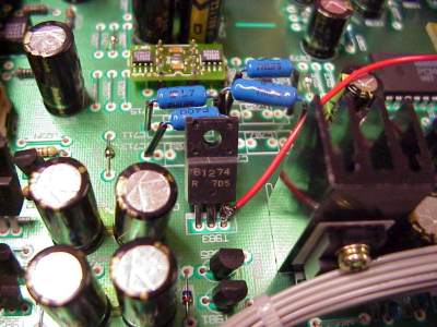
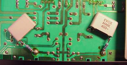
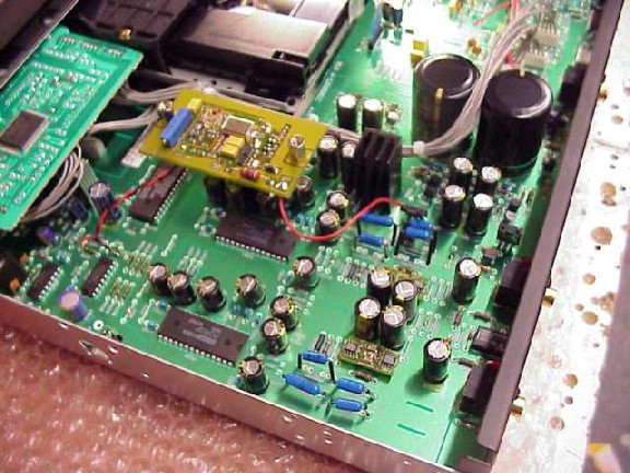
Remove top- and bottom cover by unscrewing the (many) screws. The Crystal unit is placed in a rubberbox, on the main PC Board right hand side near the front plate. Remove the Crystal unit ( X631 ). Short circuit C634 as shown on the photograph. Also break the two PCB traces as shown on the photo, use Your Dremel or a sharp knife. (Caution!). Short R635 to R634 as shown with the short red wire.
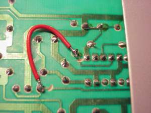
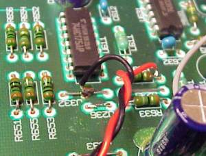
Connect LClock XO Out (Red twisted wire) to R634, the end closest to the front plate. Connect LClock XO Ground (Blue twisted wire) to The PCB GND plane at pin 7-8 of U611, top side of the PCB. Connect +12V (Single red wire) to T983, use the pin closest to the front plate. Careful not to short other pins with solder. You can tune this machine to true high-end performance by changing the OPA2604's to AD825 modules (type 3, 2 pcs.) And also bypass the DC blocking Caps (C717 and C718) with a 100n PP (i.e. EVOX-RIFA) and a good quality 100 Ohm resistor directly to the output plug. Never connect two caps directly in parallel because of the current resonance problem.
ROTEL RCD-975
|
Frequenza di clock |
11,2896 MHz |
|
Convertitore |
2x Philips TDA 1305 T |
The Crystal unit is placed in a gummibox, on the converter PC Board approximately midways on the PC Board, a couple of centimeters towards the frontpanel. We recommend you dont reuse this rubberthing when installing LClock. The Converter PC Board is loosened, by Removing the screws in each corner, and a screw holding the RCA LINE-Out plugs. Furthermore the metal screen on the rear side, is unsoldered from the RCA plugs. Take the converter PC Board carefully out of the chassis, remove the Crystal unit ( X301 ). Remove C323 and C324, they are placed right next to the Crystal unit. Cut pin 4 on U307 ( 74HCU04 ), Connect LClock Out (Red twisted wire) to pin 1 of this IC. Connect LClock Ground (Blue twisted wire) to pin 7 of U307 ( 74HCU04 ). +12V to LClock (Red single wire) is taken from J153, placed on the other PC Board, right next to the heat sink. As an extra modification, we can recommend changing the two AD711 in the analog stage, to LT1122.
ROTEL RCD-991
|
Frequenza di clock |
16,9344 MHz |
|
Convertitore |
2x Burr Brown PCM63/HDCD |
Remove top- and bottom cover by unscrewing the (many) screws. The Crystal unit is placed in a rubberbox, on the main PC Board right hand side near the front plate. Remove the Crystal unit ( X201 ). Remove C211 and C212, found right next to the Crystal Unit. Short C212 with a wirebit. Cut pins 2, 8 and 12 of U206 (74HCU04). Connect R223, the terminal closest to the CD transport to R204, the terminal away from the CD transport, and finally pin 11 on U204, using a short wire. Connect LClock XO Out (Red twisted wire) to R223, the terminal closest to the CD transport. Connect LClock XO Ground (Blue twisted wire) to pin 7 of U206. Connect +12V (Single red wire) to + terminal on C909, one of the large 4700 uF electrolytic capacitors.
Torna all'indice Indietro (E-P) Avanti (S-Z)
Prezzi e prodotti aggiornati sul nuovo sito Audiokit e-Shop cliccando qui !
Update prices & products on new e-Shop Audiokit website click Here
mercoledì 02 luglio 2014