LClockXO Istruzioni specifiche per il Montaggio
(E-P)
Attenzione, sono indicazioni indicative ! non possiamo conoscere i dettagli di ogni apparecchio
KENWOOD DP7030
Frequenza di clock
45,158 MHz
Convertitore
Sony CXD 2552
The Crystal unit is painted white, and right next to the copper bar in the middle of the converter PC Board. X1 is removed from the CD player PC Board. Remove C60, the PCB solder pad of C60, furthest away from the RCA LINE output jacks, is connected to LClock Out. (Red twisted wire). LClock Gnd (Blue twisted wire) is Connected to the tiny solderbubble next to X1. +12 V (Red single wire) is taken from + on C7 (a large black electrolytic can close to the heat sinks).
KENWOOD DP 7060
Frequenza di clock
16,9344MHz
Convertitore
Philips TDA1547 (DAC7)
Remove the topcover, by unscrewing the four screws in the side panels and the two on the rear panel. The Crystal unit is placed approximately 5 cm. from right hand edge of the main board, approximately midst between front and rear panels. Take the Main Board out by removing the four screws i the PC Board, samt de tre som holder stikkene ind to rear panel. Unplug FORSIGTIG! den whitee flexledning. Lift øverste del of connectoren opad. Vip nu the Main Board op of the CD player enclosure. Remove X2, Q41 and C94. Connect LClock Out (Red twisted wire) to the pcb solder pad of C94 closest mod the front panel. Connect LClock Gnd (Blue twisted wire) to the other PCB solder pad of C94. Connect LClock +12V (Red single wire) to W167, it is placed next to the two large electrolytic capacitors.
KENWOOD DP 7090
Frequenza di clock
16,9344MHz
Convertitore
8x Burr Brown PCM 1702
The Crystal unit X1 is placed on the main PC Board, approximately 8 cm. / 3" behind the frontpanel, just about on the middle of the board. X1 and Q31, which are placed next to X1 are to be Removed. From emitter of Q31 a red capacitor mrk. 102 lead the original clock signal to the 74HCU04 IC. Remove this capacitor, and Connect 'LClock Out' (Red twisted wire) to the PCB solder pad of the capacitor, closest to the frontpanel. LClock Gnd (Blue twisted wire) is Connected to pin 7 of the 74HCU04, or the PCB solder pad 7 of the IC drawn on the PC Board, right next to 74HCU04, in the direction towards the frontpanel, the IC is not mounted. +12 V (Red single wire) is taken from the input of the 78M05, placed on the left rear side on the PC Board.
MARANTZ CD 10
Frequenza di clock
11,2896 MHz
Convertitore
Philips TDA 1547 (DAC 7)
Remove the top plate, by unscrewing the two screws at the back panel. The original crystal 'X561' is placed on the smaller Circuit Board, elevated in the right hand side of the CD player. Carefully loosen the Circuit Board, and tilt it out of the cabinet. Remove X561, and its two companion capacitors. These are unmarked Surface Mount Devices. The only safe way You can identify them, is by following the short copper trace from the crystal (X561) pins to both of them. (On the Top Layer). They are removed by applying excessive solder to both terminals, and then alternating the solder iron, to melt both terminals solder simultanously. Connect LClock Out (Red twisted wire) to the solder pad from X561, closest to the IC marked NPC 5803APT. Connect LClock Gnd (Blue twisted wire) to the Copper Ground Plane, right next to X561. Connect LClock +12 (single red wire) to + terminal of C613, it is the closest of the red capacitors.
MARANTZ CD 52
Frequenza di clock
11,2896 MHz
Convertitore
Philips SAA7321 GP
Remove top and bottom cover, you need a Torx T10 screwdriver. Remove the Crystal unit, it is placed on det large PCB assembly, reaching down under the CD transport. The Crystal unit is placed on the side of the PC Board, furthes away from the CD transport. Mrk. 1502. Remove the two light grey SMD capacitors (microsize) on the solder side of the PC Board. They are placed right next to the Crystal unit, and are connected to this. NB! There is also another light grey smd capacitor near by, it is not connected to the crystal unit. Do NOT remove this component! SMD components are Removed by alteringly each solder terminal, in a rapid pace, so the component finally melts off. Never use force on such components, the PC Board can be damaged. LClock Gnd (Blue twisted wire) is Connected to jumper pos. nr. 9091. LClock Out (Red twisted wire) is Connected to the Crystal unit PCB solder pad closest to the front panel. +12 V (Red single wire) is taken from 78M15 pos. 6577, right hand PCB solder pad, (output) when you see the text '78M15' correctly. 78M15 is placed near the right hand corner of CD transport, on the main PC Board.
MARANTZ CD 63 SE
Frequenza di clock
16,9344MHz
Convertitore
NPC SM 5872 BS
The Crystal unit is placed on the right hand side of the main PC Board. The main PC Board is unmounted, by removing the screws holding it, and taken carefully out of ther chassis. Remove XD01, CD02 and CD03. One of the PCB solder pads on XD01 ( den closest to the rear panel ) is used to Connect Clock Out on LClock. (Red twisted wire) LClock GND (Blue twisted wire) is connected on the CD03 PCB solder pad closest to the PC Boards edge. +12V (Single red wire) is derived on the right hand PCB solder pad of Q801, it is placed right in front of the REMOTE in-out jacks on the rear panel. Connect the red wire from LClock to the right hand PCB solder pad, when you see the CD player enclosure front the front panel side.
MARANTZ CD 72
Frequenza di clock
11,2896 MHz
Convertitore
Philips SAA7350
OP originali
JRC 5532D / 5534
Moduli 825 sostitutivi
2x tipo 1 + 2x tipo 4
The Xtal unit is located on the right hand side of the main board, 15 cm / 6 in. behind the front panel. It is designated XD01. Remove XD01, CD01 and CD02. Connect LClock Out (Red twisted wire) to the solder pad from XD01, closest to the front panel. Connect LClock Gnd (Blue twisted wire) to the solder pad from CD01 closest to the nearby IC QD01. Connect red single wire (+12V) to the input of QD821, located by the rear panel, on a heatsink. It is the midst one, use the pin closest to the front panelRemove .
MICROMEGA LEADER
Frequenza di clock
11,2896 MHz
Convertitore
Philips SAA 7321 GP
Remove top and bottom cover, you need a Torx T10 screwdriver. Remove the Crystal unit, it is placed on det large PCB assembly, reaching down under the CD transport. The Crystal unit is placed on the side of the PC Board, furthes away from the CD transport. Mrk. 1502. Remove the two light grey SMD capacitors (microsize) on the solder side of the PC Board. They are placed right next to the Crystal unit, and are connected to this. NB! There is also another light grey smd capacitor near by, it is not connected to the crystal unit. Do NOT remove this component! SMD components are Removed by alteringly each solder terminal, in a rapid pace, so the component finally melts off. Never use force on such components, the PC Board can be damaged. LClock Gnd (Blue twisted wire) is Connected to jumper pos. nr. 9091. LClock Out (Red twisted wire) is Connected to the Crystal unit PCB solder pad closest to the front panel. +12 V (Red single wire) is taken from 78M15 pos. 6577, right hand PCB solder pad, (output) when you see the text '78M15' correctly. 78M15 is placed near the right hand corner of CD transport, on the main PC Board.
MICROMEGA STAGE 2
Frequenza di clock
33,8688 MHz
Convertitore
Philips SAA 7321 GP
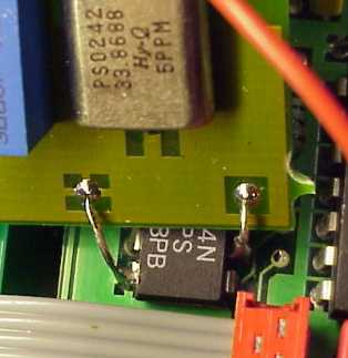
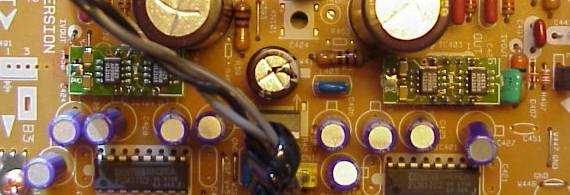
Remove the top plate, You need a Torx 10 screwdriver for this job. Remove the original crystal unit, it is placed right in front of the 'Coax Out' plug. Remove the green choke (looks like a resistor, but green) right next to the crystal unit. Also remove the yellow capacitor next to the crystal unit. Cut pin 10 of the nearest 74HCU04. Since there is no designators on MicroMega's Circuit Board, we have to use photos instead.
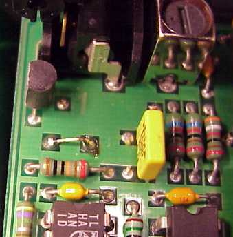
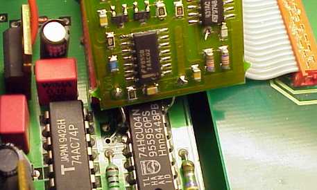
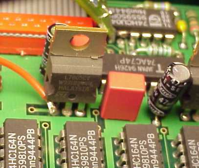
This installation shows a LClock C2, but the XO clock fits in the same manner, just using connection wires instead. Short Circuit the two solderpads from the now removed crystal unit. Connect LClock Out (Red twisted wire) to pin 9 of the 74HCU04. Connect LClock Gnd (Blue twisted wire) to pin 7 of the 74HCU04. Connect LClock +12 (single red wire) to the input of the 7805 showed. This is the left pin when reading the '7805' text correctly.
ONKYO DX 704
Frequenza di clock
33,8688 MHz
Convertitore
MN6472 (Technics MASH)
OP originali
2x NE5532 + 2x TL072
Moduli 825 sostitutivi
4x tipo 1
Remove the top cover, and rear panel, by unscrewing all visible screws. Loosen the main Circuit Board, by removing all visible screws, and squeezing the two plastic fasteners, while carefully pulling the Circuit Board out. When You can access the solder side, You are ready to start soldering. Locate the crystal unit, it is a very small cylindrical metal can part, placed in a rubber pyramid, in the rightmodt part of the main Circuit Board. Remove the Crystal Unit. Also remove its companion Capacitors C155 and C156 marked '5'. Connect LClock Out (Red twisted wire) to the solder pad from the now removed Crystal Unit, closest to the Front Panel. Connect LClock Gnd (Blue twisted wire) to the solder pad from C155, closest to the Circuit Board Edge. Connect LClock +12 (single red wire) to Q906 the 'IN' terminal, placed about 7 cm. (3 inches) closer to the Circuit Board Center.
ONKYO DX 7500
Frequenza di clock
16,9344MHz
Convertitore
Onkyo 8S-3380-1
OP originali
4x NJM 4560 SIL 9
Moduli 825 sostitutivi
4x tipo 2
Remove the top cover, and rear panel, by unscrewing all visible screws. Loosen the main Circuit Board, by removing all visible screws, and squeezing the two plastic fasteners, while carefully pulling the Circuit Board out. When You can access the solder side, You are ready to start soldering. Locate the crystal unit 'X101', it is placed about the middle of the frontmost partition of the main Circuit Board. Remove X101. Also remove its companion Capacitors C144 and C145. Connect LClock Out (Red twisted wire) to the solder pad from the now removed Crystal Unit, closest to the Front Panel. Connect LClock Gnd (Blue twisted wire) to the solder pad from C145, closest to the Circuit Board Right Hand Edge. Connect LClock +12 (single red wire) to Q901 the 'IN' terminal, placed about 10 cm. (4 inches) closer to the CD transport.
PARASOUND C/DP 1000
Frequenza di clock
16,9344MHz
Convertitore
Burr Brown PCM 67 (18 bit)
Remove the topcover on the CD player enclosure. The Crystal unit is a bit hard to locate, but it IS there! It is placed on the large PCB assembly in the middle of the CD player, right next to the PCB wire connector with the two grey wires. It is a tiny cylindric Crystal unit measuring just 2,5 m.m. in diameter and 10 m.m. length. On the Crystal unit (pos. X101) is marked 4YBH, a rather noninformative text but it IS a 16,9344 MHz crystal. Remove X101, C157 and C158. It is accomplished by removing the three wire connectors from the PC Boards right hand edge ( when you view the CD player from the front panel ), loosen screws holding the PC Board, and the nut on the Coax Out jack from the exterior. Tilt The PC Board gently out of the chassis. Connect LClock Out (Red twisted wire) to the PCB solder pad of X101 furthes away from the CD transport. Connect LClock Gnd (Blue twisted wire) to the PCB solder pad of C157, closest to the rear panel. Connect LClock +12V (Red single wire) to + on C175 on the solder side of the PC Board.
PINK TRIANGLE NUMERAL
Frequenza di clock
33,8688 MHz
Convertitore
Philips TDA1305T
Remove the top cover, for this you need a 2 m.m. hex-key and a pozidrive screwdriver. Numeral is not equipped with a Crystal unit, but instead it has a (cheap) clock generator, it is placed at the midst of the PCB assembly, which also holds the XLR and RCA jacks. It is a blank shiny square metal can of 10 by 10 m.m. There is also a clock generator on the CD transport PCB, it is purposed to run when the transport is used with another DAC the the Numeral. Don't bother tampering with this other clock generator. Remove the clock on the XLR/RCA PC Board, it has pos. X1. It is done by adding lots of solder to all four PCB solder pads, and heat them two and two changing in a rapid pace. At the same time, carefully pull the can out of the PCB in tiny steps with a finger. Connect LClock Out (Red twisted wire) to the PCB solder pad of X1, furthest away from the sharp corner of the clock generator symból on the PCB. Connect LClock Gnd (Blue twisted wire) to den PCB solder pad of X1, closest to the sharp corner. Connect LClock +12V (Red single wire) to right hand PCB solder pad (output) on U5 (7812) it is placed approximately 4 cm. towards the frontpanel starting from X1.
PIONEER PD75
Frequenza di clock
16,9344 MHz
Convertitore
Pioneer PD2028A
The Crystal unit is placed under the coppercan, situated closest to the middle of the CD player enclosure. The converter PC Board is unfastened, and taken carefully out of the chassis, the can is removed with a soldering iron. Remove X512, and R511. Short circuit C517 On IC512: Connect LClock Out (Red twisted wire) to Pin 3. Connect LClock Gnd (Blue twisted wire) to Pin 7. +12V (red single wire) is soldered to R651, no matter which side.
PIONEER PD93
Frequenza di clock
16,9344 MHz
Convertitore
Pioneer PD2028A
It is easier to access the installation site from the bottom of the CD player. Remove the bottom cover. Locate IC2, about midways between front and rear panels, in the right hand side of the main Circuit Board. Connect pin 3 to GND. Remove the wire link from pin 6 to pin 9, this is done by removing the solder, and the pushing the wirelink out of its holes. Remember to pick the wire link out of the CD player, immediately after it releases. Connect LClock Out (Red twisted wire) to Pin 9 of IC2. Connect LClock Gnd (Blue twisted wire) to Pin 7 of IC2. +12V (red single wire) is soldered to the wire link labelled +12V, some 10 cm. (4 inches) from the back panel.
PIONEER PD95
Frequenza di clock
16,9344 MHz
Convertitore
Pioneer PD2028A
Remove screws, holding the converter module in the CD player enclosure's right hand side, including the metalchassis under the PC Board. Remove all PCB wire connectors on the converter PC Board. The connectors, fastened on the chassis are unplugged. Remove all screws, som holding the converter PC Board. NB! the PC Board is fastened with adhesive pads on the middle, so you have to practice 'gentle violence' to get it out. Lift the PC Board gently out of the chassis. The Crystal unit is placed under the copper can, placed closest to the middle of the CD player enclosure. Remove this Can using a soldering iron. Remove X512 and R511. Short Circuit C517. On IC512: Connect LClock Out (Red twisted wire) to pin 3. Connect LClock GND (Blue twisted wire) to pin 7. +12V (red single wire) is soldered to R621, no matter which side.
PIONEER PDR-04
Frequenza di clock
16,9344 MHz
Convertitore
AKM4321
The Crystal unit is placed on the PC Board, also holding the RCA in/out plugs. Take this board out of the machine by removing screws holding the RCA plugs, and the PCB itself. Remove the Crystal unit ( X303 ) by use of solder wick on both sides of the PC Board. Remove the two microscopic capacitors between X303 and IC308, they are brown surface mount devices with no marking. Connect LClock Out (Red twisted wire) to the solder pad of X303, closest to the screwhole right near by. Connect LClock Gnd (Blue twisted wire) to the GND-pad of X303 on the component side. Connect LClock +12 V (Red single wire) to IC407, placed in the 45 deg. angle corner of the PC Board, use the pad, closest to the large electrolytic capacitor.
PIONEER PDS-06
Frequenza di clock
16,9344 MHz
Convertitore
PCM 1702 J
OP originali
NJM 2114D
Moduli 825 sostitutivi
2x tipo 1
Remove the screws holding the top cover, both on the sides, and on the rear panel. Remove all copper clad screws from right hand located Main Circuit Board. Also remove the screws holding the plugs to the rear panel. Push the CD tray out a bit, by first pushing the smaller of the two plastic actuator sticks. Carefully tilt the main Circuit Board out to access the solder side. Remove the Oscillator X301, it is located near the inner corner of the Main Circuit Board. Connect LClock Out (Red twisted wire) to the solder pad of X301, nearest W368. Connect LClock Gnd (Blue twisted wire) to the GND-pad of X301 - the pad nearest IC61. Connect LClock +12 V (Red single wire) to W366, about 2 cm. (<1 inch) towards the inner corner of the Circuit Board.
PIONEER PD-S505
Frequenza di clock
16,9344 MHz
Convertitore
PD 2029A
OP originali
NJM 4558
Moduli 825 sostitutivi
1x tipo 1
Remove the screws holding the top cover, both on the sides, and on the rear panel. Remove all copper clad screws from right hand located Main Circuit Board. Also remove the screws holding the plugs to the rear panel. Push the CD tray out a bit, by first pushing the smaller of the two plastic actuator sticks. Carefully tilt the main Circuit Board out to access the solder side. Remove the crystal unit 'X401' it is found right next to the D/A Converter PD2029A. Also remove the two capacitors C403 and C404. Connect LClock Out (Red twisted wire) to the solder pad of CNB3, closest to the front panel. Connect LClock Gnd (Blue twisted wire) to the solder pad of CNB3, closest to the back panel. Connect LClock +12 V (Red single wire) to + terminal on C419, about 2 cm. (<1 inch) from the back-most corner of the Circuit Board.
PIONEER PD-S507
Frequenza di clock
16,9344 MHz
Convertitore
PE8001A (come nel DV-717)
OP originali
NJM 4558
Moduli 825 sostitutivi
1x tipo 3
Remove the screws holding the top cover, both on the sides, and on the rear panel. Remove all copper clad screws from right hand located Main Circuit Board. Also remove the screws holding the plugs to the rear panel. Push the CD tray out a bit, by first pushing the smaller of the two plastic actuator sticks. Carefully tilt the main Circuit Board out to access the solder side. Remove the crystal unit 'X401' it is found 10cm (4 inches) in front of the Line Out plugs. Also remove the two capacitors C403 and C404. These are Surface Mounted Devices, and best removed by alternating the Soldering iron, in order to keep both ends melted. Then You can push the component away from the copper pad, and then pick it up with at tweezer. Connect LClock Out (Red twisted wire) to the solder pad of X401, closest to the CD transport. Connect LClock Gnd (Blue twisted wire) to the wire link labelled 'GND', right next to X401. Connect LClock +12 V (Red single wire) to LClock XO Supply (Required for this model). Remember to also connect LClock ground to the XO power supply. Best taken from the minus of the 10.000 uF Capacitor.
PROCEED PCD2
Frequenza di clock
11,2896 MHz
Convertitore
Burr Brown PCM 58P
Remove the top cover by unscrewing the six screws on the bottom side of the enclosure. The Crystal unit is placed on the vertical sidepanel mounted PCB, on the upper part, near the rear of the enclosure. Remove the Crystal unit X400, C402 and C403. Connect LClock Out (Red twisted wire) to the pcb solder pad of X400 placed downmost. (Corresponds to pin 11 on SAA7220). Connect LClock Gnd (Blue twisted wire) to the pcb solder pad of C402 placed downmost. Connect LClock +12V (Red single wire) to CR004, the upmost solder terminal. CR004 is placed approximately 2 cm. below the Crystal unit.
Torna all'indice Indietro (A-D) Avanti (Q-R)
Prezzi e prodotti aggiornati sul nuovo sito Audiokit e-Shop cliccando qui !
Update prices & products on new e-Shop Audiokit website click Here
mercoledì 02 luglio 2014